A low cost platform for benchmarking tracking systems
One published work, entirely real: the benchmarking platform of SN Computer Science 2026, the instrument that compares one optical tracking method with another.
-
Benchmarking platform
A low cost platform for benchmarking tracking systems
A custom built platform that measures how well an optical marker based system tracks a surgical tool, so that different tracking methods can be compared on accuracy, repeatability and reliability with one standardized procedure. In collaboration with Alessandro Contenti.
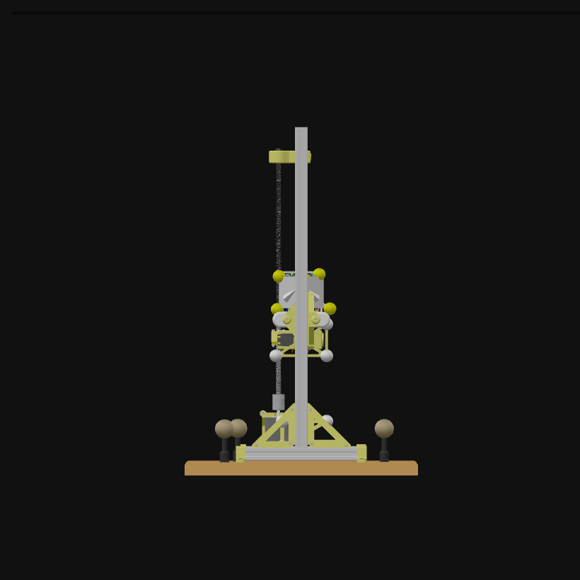
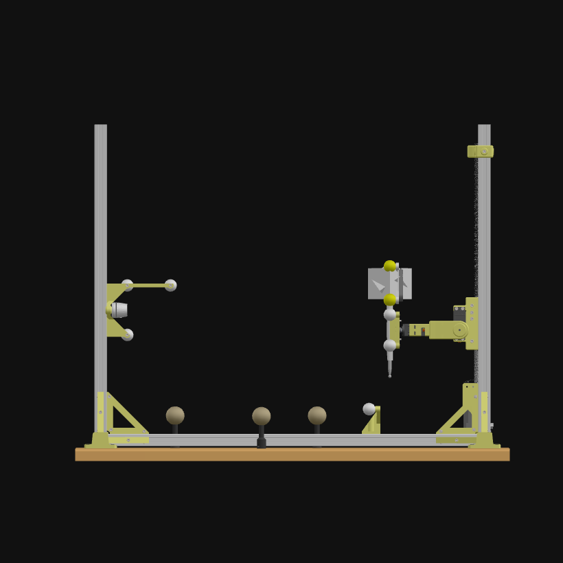
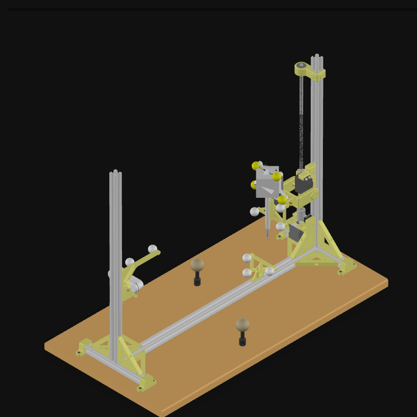
The platform of the paper: a modular aluminium frame carrying the robotic arm and the camera, with passive fiducial markers on both supports. Seven interchangeable pointers, one per marker type, mount on the last link of the arm beside the tool support, and the three calibration spheres are the ones the metrological qualification is measured in.
Tracking error in augmented surgery is usually measured in a relative and not in an absolute manner: the points collected with the instrument are aligned to their theoretical pattern by a transformation that minimises the alignment error, which nullifies or compensates any absolute error. A unique and repeatable procedure for comparing one tracking method with another was missing.
01
Mechanics and electronics
A modular aluminium frame carries a robotic arm and a camera, and both the tool support and the camera support integrate passive fiducial markers that define their reference frames. The arm moves the tool through non planar and non frontal poses, in which distance and orientation from the camera change together, while keeping the repeatability a ground truth needs.
The arm that holds the tool
- 3degrees of freedom
- 1prismatic axis
- 2revolute joints
The arm is actuated by standard stepper and servo motors, driven by a microcontroller based module interfaced with a PC command module; component specifications, CAD models and control electronics are in the Supplementary Material.
02
Evaluation metrics
Six metrics, so that any method is benchmarked in the same terms. Three are the classical ones of marker based tooltip tracking, introduced by Maurer in 1997; three were added here to cover stability while the tool stands still, the orientation of the instrument and the whole trajectory it travels.
What each metric measures
- FLE
- fiducial localization error, the localization error of the individual fiducials.
- FRE
- fiducial registration error, the residual alignment error left after pose estimation.
- TRE
- target registration error, the localization error of independent target points such as the tooltip.
- TJM
- target jitter magnitude, tracking stability measured as the oscillation of the tooltip in stationary conditions.
- TOE
- target orientation error, the discrepancy in the orientation of the tracked instrument.
- THD
- trajectories Hausdorff distance, tracked tooltip trajectory against the ground truth one, a measure of both precision and completeness.
The mathematical formulations, derivations and schematizations of the six metrics are reported in the Supplementary Material of the paper.
03
Adopted measures
Two campaigns, the camera fixed in the same position for both. Static, with the arm holding the tool in five configurations chosen to give diverse views of the tool and its markers over a significant portion of the workspace. Dynamic, with the tip following a predetermined trajectory while a video of the tool is recorded.
The size of one campaign
- 5static configurations
- 300frames captured in each of them
- 1tangential speed profile, the same for every method
Figure 3. In every frame FLE and FRE are computed when the method allows it, TRE and TOE always; the duration of the dynamic test is constant, so the number of sampled points depends on the method and each one gets a pair of THD values. Three marker based methods were run through the procedure as case studies: RGB mono with Vuforia, RGB and depth with ICP, IR mono with perspective n point.
04
Ground truth
Every metric except FRE and TJM needs one. The platform carries five reference frames, the scanner, the world, the tool, the camera and the lens, and what the metrics ask for is the pose of the tool in the lens frame. It is obtained by relating the triplets of spherical markers on the tool and on the camera through the world frame, which splits it in two.
The pose of the tool in the lens frame
(1)A transformation is written with the frame it goes to above and the frame it comes from below: T the tool, W the world, L the lens. The first factor is computed once, the world frame being rigidly fixed to the support structure; the second is obtained for each configuration from the scans of the tool and world pair. For the trajectory metric the ground truth is instead the programmed tool path, aligned to the tracked one with ICP.
The chain takes the tip position and the lens position from the CAD models and neglects the deviation between the programmed and the executed trajectory. Its residual error sources are listed one by one in the paper: printing tolerance, scanner accuracy, Gaussian fitting of the sphere centres, ICP residual and the positioning error of the stepper driven axes.
05
Metrological qualification
The ground truth is itself measured. All five configurations were replicated in front of an industrial optical coordinate measuring system, and every spherical feature was acquired by it and by the operational scanner alike. Three Grade 5 ceramic spheres of 30 mm define the local frame the two acquisitions are compared in, so no global alignment can bias the comparison, and the operational acquisition was repeated ten times per configuration.
Repeatability, uncertainty, and the bound they set
(3)(4)(6)Δq is the discrepancy along one axis between the sphere centre measured by the metrology grade system and the one measured by the operational scanner, for a given sphere, configuration and repetition; N is the number of samples aggregated over the three. s is the repeatability, u the combined standard uncertainty, which adds to it the contribution of the metrology grade system as a type B component, and U the expanded uncertainty at a 95 percent coverage level through the coverage factor k, about 2. The bias, the mean of the same discrepancies, was estimated and deliberately not corrected.
Table 1. Repeatability between 0.195 and 0.240 mm per axis, expanded uncertainties between 0.391 and 0.480 mm, and an aggregated three dimensional expanded uncertainty of 0.766 mm: a difference in tracking performance below about 0.7 to 0.8 mm has to be read in the light of that bound. What the platform returns for a tracking method is therefore accuracy, repeatability and a stated uncertainty, which in the perspective drawn by the paper makes it a quantitative pre-selection tool, used before a system is integrated and validated in a clinical workflow.
Component of the platform